
” How to use a RGB LED with Arduino | Tutorial.” How to Mechatronics. Grumpy_Mike (2010, October 20). Re: RGB LED Common Cathode versus Common Anode. of the 3 colors and one common cathode or anode depending of the RGB LED type. The results:Ĭheck out a simulation of this project on AutoDesk 123D circuits. In this Arduino Tutorial we will learn what RGB LED is and how to use it.
#RGB COMMON ANODE ARDUINO SERIES#
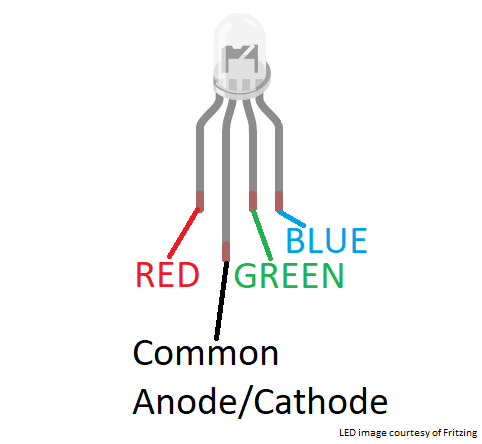
The red, green, and blue LEDs are then connected to pins 3, 5, and 6 using a 220 resistors in series to limit current, preventing the LEDs from being damaged. The positive pin of the RGB LED connects to the VCC pin of the Arduino to provide power. This concept is repeated for other color transitions. The pins of a common anode RGB LED are shown by Figure 2. As it does that, the LED will cycle through all the possible color combinations, giving off the color changing effect.Īs the RGB LED transitions from green to red, the pin value decreases for green and increases for red while blue stays 0 (OFF). The logic behind this sketch is that the LED will transition from green to red, then to blue and back to green. I used 220 ohm dropping resistor for all the LED segments but of course you can fine tune this and use different values for the individual segments. This way you can see how to drive both of them. One is a common cathode device and the other is a common anode RGB LED. ino file can be found on GitHub as RGB_LED.ino. I’ve wired two RGB LEDs to the Arduino for this demo. You will need:Ģ20 ohm resistors How you hook it up: RGB LED connected to an Arduino Uno.

For this project, we will use the common cathode. A common-anode RGB LED has four leads: one anode, and one cathode for each color. For the common cathode RGB LED, one will connect the cathode to GND and the remaining pins to resistors and output pins (Grumpy_Mike, 2010).

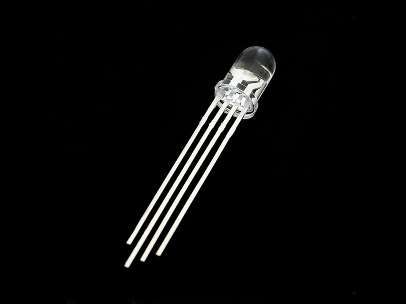
For the common anode RGB LED, one will connect the anode to a 5V source and the remaining pins to resistors and output pins. In both LEDs, the longer pin sticking out represents the common anode or cathode. The red, blue and green diodes are represented by R,G and B respectively. There are 2 types of RGB LED: (1) common anode RGB LED and (2) common cathode RGB LED where the three diodes are connected to a “shared” terminal be it positive or negative. By tinkering how much red, green and blue to be added to the palette, we end up with 256*256*256= 16,777,216 different colors ( not all perceive by the human eye of course). The SparkFun Library has now been updated as of for this through hole tricolor LED. Remember how we can use analogWrite() to control how much voltage delivered to a pin? The values 0-255 correspond to 256 different voltage levels delivered to an LED and this will result in 256 different magnitudes of red, green and blue. These 3 colors alone are able to produce around 16 million different colors thanks to PWM and the laws of permutation. 5 mm common-anode RGB LED Piezo buzzer 5V 1A USB port wall power supply (optional) 4-digit 7-segment display with I2C backpack (1.2 inch or 0.56 inch. RGB LEDs house 3 different color-emitting diodes (red, blue and green) and they combine these 3 colors to produce a spectrum of vibrant hues. RGB LED stands for red, green and blue LED. This time around, we will do the same thing but with an RGB LED. Last time we talked about fading an LED and how it is achieved by PWM.


 0 kommentar(er)
